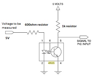
General Purpose Relay Wiring Diagram Schematic

Image: 72_1285622555.jpg (313×249) Simple circuit, Electronics
File Type = .PDF
Credit To @ www.pinterest.com
PDF Download
Open new tab

Image: Stepper motor controller circuit diagram using IC's IC
File Type = .PDF
Credit To @ www.pinterest.com
PDF Download
Open new tab

Image: Electronics DIY Quality Electronic Kits, Electronic
File Type = .PDF
Credit To @ www.pinterest.com
PDF Download
Open new tab

Image: Best Relay Wiring Diagram 5 Pin Bosch Endearing Enchanting
File Type = .PDF
Credit To @ www.pinterest.com
PDF Download
Open new tab

Image: Generalpurpose addon preamplifier. Electronic
File Type = .PDF
Credit To @ www.pinterest.com
PDF Download
Open new tab

Image: Inspirational Morris Minor Wiring Diagram with Alternator
File Type = .PDF
Credit To @ www.pinterest.com
PDF Download
Open new tab
The red LED and the DC fan now shut off and the green LED and the DC motor now turn on and operate.

General purpose relay wiring diagram schematic. 94 Camaro Fuel Pump Wiring Diagram Free Download • Oasis-dl.co 2001 camaro wiring diagram data wiring diagrams \u2022. OMRON provides General-purpose Relays, I/O Relays, Power Relays, Latching Relays, and Ratchet Relays. DPDT Relay Wiring Diagram How to Build a Relay Driver Circuit Types of Relays Relay Terminals Relay Wiring Diagrams Te Connectivity Potter Brumfield Krpa 11dn 24 Power;
The real benefit behind a relay is more than automation. Magnecraft General Purpose Relays!"#$%& '$"()"*%(!+, 70-750EL8-1, 70-750EL11-1, 70-781D5R-1A, and 70-781T-1 Wiring Diagrams 70-750EL11-1 32 24 31 21 34 22 12 11 14 A2 A1 10 7 5 9 3 8 4 16 2 1 6 1 8 9 7 3 4 0 2 5 Coil Bus Jumper MODULE INPUT INPUT IEC NEMA 70-750EL8-1 A2 22 24 12 14 11 21 Coil Bus Jumper A1 8 7 6 5 4 3 2 1 220v 8 pin relay wiring diagram. Variety of 12 volt solenoid wiring diagram.
This circuit has frequency response range from 16Hz to 30kHz. Easy online ordering for the ones who get it done along with 24/7 customer service, free technical support & more. Allen Bradley Ice Cube Relay Wiring Diagram 7 13 Kenmo Lp De Simple fast conversion of the 700 series control relay contacts from either no normaly open to nc normaly closed or visa versa. 12 volt relay wiring schematic.
By Circuit Diagram This general purpose power supply can e used for supply output voltages from 1 to 35V. Assortment of 12 volt relay wiring diagram. 12 Volt Relay Wiring Diagram 12 volt relay wiring diagram scribd relay wiring diagram used for accessories in a 12volt system a relay is typically used to control a ponent that draws high amperage the relay relay diagrams quick reference the12volt how to wire relays and relay diagrams a quick reference of dozens of automotive relay. General purpose alarm circuit diagram has been viewed 765 times which last viewed at 2020-06-16 16:49:58 and has been downloaded 2 times which last downloaded at 2016-03-28 09:44:58 added by Leah on 05 Jul, 2014.
Krpa 11dn 24 Potter Brumfield Power Relay Dpdt 10a; Hinged relays switch contacts by the rotating movement of an armature around a fulcrum. Krpa 14dn 24 Potter Brumfield Te Connectivity Power MKS2PIDC MKS2PI DC B.
A hinged relay is shown below as an example. General Purpose Relays Types K, R, N, and C Catalog 8501CT0301R7/08 2008 Class 8501 CONTENTS Description. 3/16” Silver cadmium oxide . Car qook automotive dc 12v 12 volt 30a amp spdt wiring power relay.
Looking for DAYTON 120VAC Coil Volts, General Purpose Relay, 10A @ 277VAC/10A @ 28VDC Contact Rating, Octal (5X827)? This pinout image is only a 2-pole diagram for room on the page purposes, but you can get the picture here with this one since a 3-pole will just have 1 more set of contacts. We collect this best photo from online and choose one of the best for you. Krp 11dn 24 Potter Brumfield Te Connectivity Power;
The line transformer should be selected to give about 1.4 times the desired output voltage from the positive side of filter capacitor C1 to ground. The purpose of a relay is to automate this power to switch electrical circuits on and off at particular times. This circuit uses cheap 1/4-W resistors, no high precision needed so 5%-tolerance of carbon or metal film units is good enough. Allen bradley 700 relay wiring diagram .
The square relay pinout shows how the relay socket is configured for wiring. A wiring diagram is a simplified traditional pictorial depiction of an electrical circuit. Potter Brumfield Relay Wiring Diagram Download Wiring; 46 out of 100 based on 436 user ratings The general purpose alarm circuit diagram can be download for free.
A wide array of coil voltages and contact configurations ensure there is a D series relay for every control circuit design application. Relay 8 pin wiring diagram datasheet cross reference circuit and application notes in pdf format. General-purpose Relays transfer signals through a mechanical action. When the relay receives 12 volts of power, the relay snaps from the NC position to the NO position.
A relay is an electrically operated switch. This circuit and wiring diagram: Grainger's got your back. Schematic Diagrams Viewed from Terminal End ..
700-HA Tube Base Bulletin 700-HA Tube Base Relays are general purpose relays ideally suited for applications with machine tool, pulp and paper, and transportation OEMs. This is a schematic diagram of general-purpose audio frequency (AF) amplifier circuit. For Control Panel A wide range of products are available for the purpose of sequence control to direct load switching, which will suit for various applications depending on the control method or environment inside of a panel. The D series ice cube general purpose relays provide excellent functionality and are ideal for any application from controlling smaller loads, to those requiring high current-carrying capacity.

Image: Arduino Light Sensor Circuit diagram using LDR and Relay
File Type = .PDF
Credit To @ www.pinterest.com
PDF Download
Open new tab